This is a design for power supply circuit. This circuit can produce source voltage 5V. This circuit is built by TTL IC’s. But this design is simple design. This is the figure of the circuit.
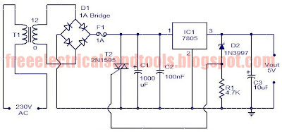
For circuits using TTL ICs the supply voltage is a great concern and a slight increase in supply from the rated 5V may damage the IC. Using fuses alone does not solve the problem because a fuse may take several milliseconds to blow off and that’s enough time for the IC to get damaged. In this circuit a crowbar scheme is used in which a triac short circuits the power supply and burns the fuse.
The burning time of the fuse is not a concern because the power supply is already shorted by the triac and the output voltage will be zero. Operation of the circuit is when the output voltage exceeds 5.6 volts the zener diode D2 conducts and switches ON the triac T1.Now T1 acts as a closed switch, shorting the circuit. The output voltage drops to zero and fuse gets burned off. The trip voltage can be varied by varying the values of D2 and R2. Since the switching of triac takes place within few micro seconds there will be no damage to the TTL ICs or any other such voltage sensitive components in the load circuit. For the transformer T1 can be a 230 V AC primary, 12v secondary, 2A step-down transformer. All capacitors must be rated at least 25V. If 1A Bridge is not available, make one using four 1N4007 diodes.


