This is a circuit of negative resistance circuits. All of the preceding circuits rely on RC time constants to achieve resonance. LC combinations can also be used and offer good frequency stability, high Q and fast starting. In the circuit, signal input is control and amp using op amp LF353. This is the figure of the circuit.
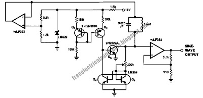
In this circuit, a negative resistance configuration is used to generate the sine wave. The Q1-Q2 pair provides a 15 μA current source. Q2's collector current sets Q3's peak collector current. The 300 kΩ resistor and the Q4-Q5 LM394 matched pair accomplish a voltage-to-current conversion that decreases Q3's base current when its collector voltage rises. This negative resistance characteristic permits oscillation. The frequency of operation is determined by the LC in the Q3-Q5 collector line. The LF353 FET amplifier provides gain and buffering. Power supply dependence is eliminated by the zener diode and the LF353 unity gain follower. This circuit starts quickly and distortion is inside 1.5%.

In this circuit, a negative resistance configuration is used to generate the sine wave. The Q1-Q2 pair provides a 15 μA current source. Q2's collector current sets Q3's peak collector current. The 300 kΩ resistor and the Q4-Q5 LM394 matched pair accomplish a voltage-to-current conversion that decreases Q3's base current when its collector voltage rises. This negative resistance characteristic permits oscillation. The frequency of operation is determined by the LC in the Q3-Q5 collector line. The LF353 FET amplifier provides gain and buffering. Power supply dependence is eliminated by the zener diode and the LF353 unity gain follower. This circuit starts quickly and distortion is inside 1.5%.


