This circuit is design that can control AC loads such as Lights, Fans etc through the remote handset of TV. The circuit uses the popular timer IC 555 in the Bistable mode. Here’s the figure of the circuit;
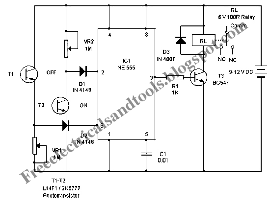
In this circuit, the Bistable mode output IC555 keeps two states, either low or high. When a negative pulse is applied to the trigger pin 2 of 555, the output turns high and remains as such in the latched state. If a positive pulse is applied to the Threshold pin 6, its output turns low and remains as such. This property is used to control the AC load. The negative and positive pulses are given to the trigger and threshold pins of 555 through the light activated phototransistors T1 and T2. The collector of T2 is connected to the trigger pin 2 through diode D1. Similarly the emitter of T2 is connected to the threshold pin 6 through diode D2. When the IR beam of remote is focused momentarily to T2, it conducts and takes the trigger pin 2 to ground potential. This triggers IC1 and its output goes high. T3 then conducts and relay turns on. Load connected to the NO contacts of the relay gets electrical continuity and turns on. When the IR beam is focused on T1, Current passes from its emitter into the threshold pin6 and the output of IC1 turns low and the relay de-energize to switch off the load.


