My Geo Map

Sponsor Links

AmericasBest.com
Showing posts with label Lamp. Show all posts

27 June 2020

Brake Lights Schematic Circuit

This is a for a cars about  the break lamps. They have a subdivision of the green circuit with its own in-line 35 amp fuse supplied by the white/brown (ignition relay) circuit feeding things like heated rear window, indicators, heater fan and tach, which leaves the original green circuit fuse (2nd one up in the four-way fuse block) feeding things like reverse lights, stop lights, washers, wipers, and circuits associated with the seat belt warning lamp and time delay buzzer. This is the figure of the diagram circuit.

04 September 2013

Security Light & Switch Circuit Using PIR Sensor


This is a design circuit for security light and switch circuit using PIR Sensor. SB0061 is a pyroelectric sensor module,developed for human body detection. A PIR detector combined with a fresnel lens are mounted on a compact size PCB together with an analog IC (SB0061) and limited components to form the module. High level output (3.3V) of pre-settable variable width (5Secs -18 Minutes) is provided. This is the figure of the circuit;


Circuit diagram of the PIR Motion Sensor Light and Switch based on SB0061 shown here can be used for security or corridor lighting in power saving mode. The 12V DC supply required for the whole circuit can be fed from any standard 12V ac mains adaptor/battery.

Working of the circuit is simple and straight forward. When any movement is detected within near 5-6 metres, around 3.3 Volt is appeared at the base of Transistor T1 and it conducts to fire the next relay driver transistor T2. As a result, the 12V DPDT relay is energised to power the White LED through current limiting resistor R3. Spare relay contacts can be used as a switch to control any suitable external load. The white LED and the relay remains ON for a duration based on the mono time setting in SB0061, ie from 5 Secs to 18 Minutes.

15 July 2013

1uS Light Pulse Receiver Circuit With Post Amp

Here’s a design circuit for light pulse receiver circuit that is used to detect very weak light pulses lasting 1uS. In the figure at below is a figure to show the schematic diagram circuit;


This circuit uses a tuned LC feedback network to provide high sensitivity while giving high ambient light immunity. A post voltage amplifier is included with a gain of about X20. The circuit is described in more detail in the receiver section of my Handbook of Optical Through the Air Communications.  Note: The LF357 op amp is no longer available, this circuit is for reference only.

19 December 2012

Sequential Brake/Turn Lights Circuit


This is a design circuit for allows up to 16 LED clusters illuminate in bar-mode sequence. LED sequencing will start when the Brake pedal is pressed (or Turn Lights are switched-on) and, when the last cluster illuminates, all LED clusters will remain steady on until the Brake pedal is released or Turn Lights are switched-off. This is the figure of the circuit;


How this circuti operate?
R5 and D1 are optional: they could be of some utility in monitoring the sequence frequency set by means of R3.Clusters can be formed by up to 12 LEDs as shown in the circuit diagram, right side. Common cluster types usually range from 5 to 10 LEDs. Up to 16 of these cluster driver circuits, each formed by the LEDs, two transistors and three resistors can be built and connected to the progressively numbered outputs of IC2 (the first eight clusters) and IC3 (the remaining clusters). If a number of clusters up to 8 is required, IC3 can be omitted.

Constant output current value for the LEDs can be changed by varying R10.
The formula is: R = 0.6/I (I expressed in Amperes). Use high brightness, high efficiency red LED types of suitable size and change R10 value to suit LED's Absolute Maximum Ratings. The main circuit, formed by the three ICs and related components is permanently wired to the supply (and D1 will flash) but its 12V positive supply can be wired after the main switch of the car, or an on/off switch can be added.

02 February 2011

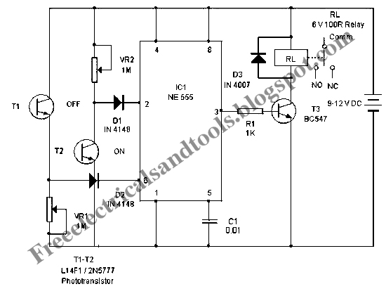
Light Controlled Bistable Circuit

This circuit is design that can control AC loads such as Lights, Fans etc through the remote handset of TV. The circuit uses the popular timer IC 555 in the Bistable mode. Here’s the figure of the circuit;


In this circuit, the Bistable mode output IC555 keeps two states, either low or high. When a negative pulse is applied to the trigger pin 2 of 555, the output turns high and remains as such in the latched state. If a positive pulse is applied to the Threshold pin 6, its output turns low and remains as such. This property is used to control the AC load. The negative and positive pulses are given to the trigger and threshold pins of 555 through the light activated phototransistors T1 and T2. The collector of T2 is connected to the trigger pin 2 through diode D1. Similarly the emitter of T2 is connected to the threshold pin 6 through diode D2. When the IR beam of remote is focused momentarily to T2, it conducts and takes the trigger pin 2 to ground potential. This triggers IC1 and its output goes high. T3 then conducts and relay turns on. Load connected to the NO contacts of the relay gets electrical continuity and turns on. When the IR beam is focused on T1, Current passes from its emitter into the threshold pin6 and the output of IC1 turns low and the relay de-energize to switch off the load.

26 August 2010

73 MHz Hallogene Lamp Radio Controlled Circuit


This is a circuit for hallogene lamp radio control. This circuit has purpose of it is to control the power state of a hallogene lamp by a remote control. When we press the push button of the remote control, the power state of the lamp will be changed, so, if the lamp was turned on, it will turned off and if it was turned on, it will turned off. If we press to the button another time, the same action will be occure. When the button is pressed, a LED indicator lights on the remote control. This is the figure of the circuit;


The system is consisted by two separate circuit. One is the remote control, or the emmetor. The other is the receptor, or the hallogene lamp controller. We plug the input of the lamp controller circuit to the 120VAC source of the sector to supply it. The lamp must be pluged to the output of the circuit to be supplied and controlled. The controller circuit has also an antenna to receive the signal of the remote control. The remote control has also an antenna to transmit the signal to the controller circuit and have to be powered by a 9V battery. Two things important for my circuit are not mentioned in the schematic. There are about the two logic component. The first one is the Schmitt trigger NOT gate (74LS14). Its Vcc pin must be connected to the output of the +5V regulator (7805). And its GND pin must be connected to the ground of the circuit. The second one is the JK Flip-Flop (74LS76). Its Vcc pin must be connected to the output of the +5V regulator (7805). And its GND pin must be connected to the ground of the circuit.

08 June 2010

Soft Light Dimmer Circuit


This is circuit of soft light dimmer. This circuit uses the IGBT STGP10N50A and the TS555 timer as main components. This is the figure of the circuit;


The timer is triggered on the zero crossing voltage pulse. The time constant is determined by C5/R14+R15 that is used to determine the conduction angle. The T2 – T3 inhibits the power switch until the auxiliary supply voltage reaches 8V to guarantee that the gate of the IGBT receives correct voltage level.

R5 is the current sense resistor that is used for the short circuit and over-current protection. The gate of the IGBT will taken low and turn off, when the voltage across R5 reaches the sensitive gate thyristor gate trigger voltage.  At the same time the timer will reset. This current limiting also provides  protection against excessive in-rush current and automatic soft-start. [Source: STMicroelectronics Application Note]

08 December 2009

40 LED Bicycles Light Using 555 Timer IC


This is a design circuit for flashing bicycle light powered with four C, D or AA cells (6 volts). This circuit is work with based on 555 timer IC for controller. This is the figure of the circuit.


Two sets of 20 LEDs will alternately flash at approximately 4.7 cycles per second using RC values shown (4.7K for R1, 150K for R2 and a 1uF capacitor). Time intervals for the two lamps are about 107 milliseconds (T1, upper LEDs) and 104 milliseconds (T2 lower LEDs). Two transistors are used to provide additional current beyond the 200 mA limit of the 555 timer. A single LED is placed in series with the base of the PNP transistor so that the lower 20 LEDs turn off when the 555 output goes high during the T1 time interval. The high output level of the 555 timer is 1.7 volts less than the supply voltage. Adding the LED increases the forward voltage required for the PNP transistor to about 2.7 volts so that the 1.7 volt difference from supply to the output is insufficient to turn on the transistor.

15 October 2009

Set or Reset Flip Flop Circuit

The circuit in below is an example of a set/reset flip flop using discrete components. This circuit is built by some components which is low cost and there is in electronic store. This is the figure of the circuit.


When power is applied, only one of the transistors will conduct causing the other to remain off. The conducting transistor can be turned off by grounding it is base through the push button which causes the collector voltage to rise and turn on the opposite transistor.

Bi Stable Flip Flop Circuit

This circuit is almost same with the circuit before. But, in this circuit there are two samples for the same circuit. It is two examples of bi stable flip flops which can be toggled between states with a single push button. This is the figure of the circuit.


When the button is pressed, the capacitor connected to the base of the conducting transistor will charge to a slightly higher voltage. When the button is released, the same capacitor will discharge back to the previous voltage causing the transistor to turn off. The rising voltage at the collector of the transistor that is turning off causes the opposite transistor to turn on and the circuit remains in a stable state until the next time the button is pressed and released. Note that in the LED circuit, the base current from the conducting transistor flows through the LED that should be off, causing it to illuminate dimly. The base current is around 1 mA and adding a 1K resistor in parallel with the LED will reduce the voltage to about 1 volt which should be low enough to ensure the LED turns completely off.

10 September 2009

A Dice Circuit Using LED

This is a design circuit for a game a dice. This circuit uses 7 LED to simulate the rolling of a dice after the Roll button is pushed. It has a slowdown feature so that you can see the 'rolling' of the dice slowing down and then stop. This is more satisfying than the usual LED dice circuit which just stops after the button is released. This circuit is work with based on 555 IC and 14017. IC 14017 is decade counter. This is the circuit figure.


The principle work of the circuit is when the switch is turned on Q4 is turned off (its base is pulled high by the 3.3M ohm resistor) and the 555 oscillator is not oscillating. Pressing the ROLL switch immediately charges the 470nF capacitor, Q4 is turned ON and the 555 starts to oscillate. The 470nF gradually discharges via the 10M ohm and 3.3M ohm resistors and turns Q4 off. The 555 is connected as an oscillator. The frequency of oscillation is generally independent of the potential difference across the pins. However, as Q4 turns off the frequency becomes dependent on the voltage. The counter CP0 is advanced by a LOW to HIGH transition from pin 3 of the 555 to pin 14. The first six outputs from the 14017 labeled are labeled by O0 to O5. The next output O6 from pin 5 is connected to the Reset pin 15.


LED Driver Circuit Delivers Constant Luminosity

This is a design of LED driver circuit. This circuit is work with based on 2two transistor. This is the figure of the design circuit.


The operation of the circuit is begin from the output current is almost constant over an input-voltage range of 1.2 to 1.5V and is insensitive to variations of transistor gain. Transistors Q1 and Q2 form an astable flip-flop.R1 and C define the on-time of Q2. During that time, Q1 is off, and the voltage at the base of Q1 and the current in inductor L ramp up. When the voltage at the base of Q1 reaches approximately 0.6V, Q1 turns on, and Q2 turns off. This switching causes “fly back” action in inductor L. The voltage across the inductor reverses, and the energy stored in the inductor transfers to the LED in the form of a down-ramping pulse of current. During fly back time, voltage across the LED is approximately constant. The voltage for yellow and white LEDs is approximately 1.9 and 3.5V, respectively. When the current through the LED falls to zero, the voltage at the collector of Q2 falls sharply, and this circuit condition triggers the next cycle

25 August 2009

Aircraft Warning Light Circuit

This is a design and low cost circuit that can be used for implementing a warning light on the top of tall structures as a warning for low flying aircrafts. It is usually such lights are just stay glow type. Our light in this circuit is a flashing type, and surely this will draw more attention and of course add more safety. This is the figure of the circuit.


This operation of the circuit is begin when the AC main is switched on the bulb will get supply and it will glow. When the bulb glows the LDR adjacent to it gets illuminated and it’s resistance drops. The LDR should be mounted at some place near to the bulb so that when bulb glows the light falls on the LDR. This will increase the voltage drop at the base of transistor Q1 and it goes on. When Q1 is on the relay is activated and trips the contacts to make the bulb off. Now the LDR resistance increases and the voltage drop across base of Q1 decreases to make it off. The relay will be de-energized and the bulb glows. This cycle repeats to produce a continuous flashing of the bulb. Since the capacitor C1 is connected across the relay the relay will remain activated for some more time even after the transistor Q1 is OFF, making the bulb to stay off for some more time. Set up the circuit as said above and power up. Then adjust the POT R2 so that the bulb starts flashing. Done! The circuit is ready.


20 August 2009

Night Security Light Circuit

This is a design simple circuit switches on a light around 2 hours after midnight, the time at which most of the robberies taking place. This circuit is work based on CMOS IC and LDR system. This is the figure of the circuit.


This is the explanation for the operation of the circuit. This simple circuit is build around a CMOS IC 4060 to obtain the required timing. During day time the LDR has low resistance and keeps the pin 12 of the IC1 high, preventing the IC1 from oscillating. When it is dark the LDR resistance becomes high and the pin 12 of IC1 becomes low and the IC starts oscillating, which indicated by the flashing of LED D3.

The values of the timing components R1, R2, C4 are so selected that the out put pin3 of IC1 goes high after 8 hours. That means the high output drives the triac to switch on the lamp around 2, 0 clock. At morning, the LDR resistance drops and the pin 12 of IC1 goes high and stops the oscillation, making the lamp OFF. The switch S1 can be used to manually ON the lamp. The capacitor C2 prevents false triggering. The LDR can be general purpose LDR. The light sensitivity can be adjusted using the preset R6. The IC1 must be mounted on an IC holder.

Micro Flasher Circuit Using 555IC

This is a simple and compact flasher circuit that can be used where ever a flashing LED is needed. The circuit finds application in flashing beacons, alarms automobile and more. The circuit is nothing but an astable multi vibrator based on IC NE 555 (IC1). This is the figure of the circuit.


The frequency of the oscillation depends on the values of R1, R2, R3 and C2. The LED glows when the out put (pin3) of IC1 goes high. The IC1 NE 555 can easily drive a LED. The resistor R4 acts as a current limiter for LED. The circuit is powered by a 6V battery or 6V DC power supply. If you don’t need frequent changes in the flashing rate use a preset for R2 and set it for the required rate. The capacitor C2 must be rated 10V.

Light Activated Switch Circuit Using LM311

This is a design circuit diagram of a light activated switch. This circuit is based on National Semiconductors comparator IC LM 311 and a LDR for operation. This is the figure of the circuit.


The circuit is based on a voltage comparator circuit wired around IC 1. The non-inverting in put of IC1 is given with a reference voltage of 6V using resistors R3 and R4. The input to the inverting input will be the voltage across the LDR that is light dependent. At darkness the resistance of the LDR will be high and so do the voltage across it. At this condition the voltage at the inverting input will be higher than the reference at non inverting pin and the out put of the comparator will be low(~o V). Adjust POT R1 to set the desired light intensity for switching the relay. For this illuminate the LDR with the desire intensity light.

The relay will be either on or off. Adjust POT R1 slowly so that the state of the relay changes. That’s it. Now the circuit is set for the given intensity of light. When the LDR is illuminated, its resistance drops and so do the voltage across it. Now the voltage at inverting input will be lower than that at non inverting input and the out put of the comparator goes high (~12 V). This makes transistor Q1 on and it drives the relay. As a result we get a relay switching according to the intensity of the light falling on the LDR.
You can use either a 12 V battery or a well regulated & filtered 12V DC mains operated power supply. The pin out of LM311 is also given together with the circuit diagram. The pin 5&6 (Balance & Balance/Strobe) of IC LM311 are shorted to minimize the chance of oscillations.

Aircraft Warning Light Circuit

This is a design and low cost circuit that can be used for implementing a warning light on the top of tall structures as a warning for low flying aircrafts. It is usually such lights are just stay glow type. Our light in this circuit is a flashing type, and surely this will draw more attention and of course add more safety. This is the figure of the circuit.


This operation of the circuit is begin when the AC main is switched on the bulb will get supply and it will glow. When the bulb glows the LDR adjacent to it gets illuminated and it’s resistance drops. The LDR should be mounted at some place near to the bulb so that when bulb glows the light falls on the LDR. This will increase the voltage drop at the base of transistor Q1 and it goes on. When Q1 is on the relay is activated and trips the contacts to make the bulb off. Now the LDR resistance increases and the voltage drop across base of Q1 decreases to make it off. The relay will be de-energized and the bulb glows. This cycle repeats to produce a continuous flashing of the bulb. Since the capacitor C1 is connected across the relay the relay will remain activated for some more time even after the transistor Q1 is OFF, making the bulb to stay off for some more time. Set up the circuit as said above and power up. Then adjust the POT R2 so that the bulb starts flashing. Done! The circuit is ready.


03 August 2009

Street Light Circuit Using LDR System

This is a design for circuit diagram of a street light that automatically switches ON when the night falls and turns OFF when the sun rises. In fact you can this circuit for implementing any type of automatic night light. This circuit is based operation on LDR system. This is the figure of the circuit.


For operation this circuit, it is use an LDR to sense the light. When there is light the resistance of LDR will be low. So, the voltage drop across POT R2 will be high. This keeps the transistor Q1 ON. The collector of Q1 (BC107) is coupled to base of Q2 (SL100).So Q2 will be OFF and so do the relay. The bulb will remain OFF. When night falls the resistance of LDR increases to make the voltage across the POT R2 to decrease below 0.6V. This makes transistor Q1 OFF which in turn ON Q2. The relay will be energized and the bulb will glow.

In POT R2 can be used to adjust the sensitivity of the circuit. You can use bulb of any wattage, provided that relay should have the sufficient rating. The circuit can be powered from a regulated 9V DC power supply. The relay K1 in this circuit can be used a 9V SPDT relay.

Brightness Controller Lamp Circuit

This is a design for control the brightness lamp. The circuit can be used to control the brightness of low power incandescent lamps. The circuit is based on IC NE555. This is the figure of the circuit.


The IC is wired as an astable multi vibrator with variable duty cycle. The output of IC is connected to the base of transistor Q1.The Q1 drives the lamp. The duty cycle of the multi vibrator can be varied by varying the POT R4.As a result, the brightness of the lamp varies according to the position of the POT R4.The same circuit can be also used for speed control of small DC motors. The IC1 must be mounted on a holder. The lamp L1 can be a 6V / 200 mA lamp. The switch S1 can be SPST ON/OFF switch.

8 Watt Flouroscent Lamp Driver Circuit


This is a design circuit of a simple flouroscent lamp driver circuit based on two transistors. The circuit uses capacitive ballasting for driving the tube. An 8 Watt standard flouroscent tube can be efficiently driven using the circuit.


The two transistors (2SC1983) with associated components form an oscillator around 1KHz. The oscillator is wired so that saturation conditions of the transistors are prohibited. This adds on to the efficiency of the circuit. The circuit produces a clean sine wave with very less noise. The winding details (no of turns) are given in the circuit. Use 0, 8 mm diameter enameled copper wire for primary and 0, 4 mm diameter enameled copper wire for secondary. The core can be a ferrite core. The primary should be wound first and secondary on top of it. The circuit is use a 12 V battery or 12 V DC power supply as the DC voltage source.

Advertisement