This is a design circuit for Dog Repellent Circuit Schematic diagram. When we hear the word “Ultrasonic" we often refer it to bats and dolphins communication. Technically, “Ultrasonic" applies to sound that is anything above the frequencies of audible sound, and includes anything over 20kHz. Frequencies used for medical diagnostic ultrasound scans extend to 10 MHz and beyond. This dog repellent ultrasonic circuit will chase away angry dogs. It comprises of a 555 timer IC, a speaker/piezoelectric and a little ferrite transformer. This is the schematic diagram.
My Geo Map

Sponsor Links

Showing posts with label Inverter. Show all posts
Showing posts with label Inverter. Show all posts
13 May 2020
04 September 2013
Soldering Iron Voltage Inverter Circuit
Here’s a
design circuit for a simple 12 V inverter for using
a small soldering iron (25W, 35W, etc) in the absence of mains supply. It uses
eight transistors and a few resistors and capacitors. Transistors T1 and T2
(each BC547) form an astable multi vibrator that produces 50Hz signal. The
complementary outputs from the collectors of transistors T1 and T2 are fed to
pnp Darlington driver stages formed by transistor pairs T3-T5 and T4-T6 (utilizing
BC558 and BD140). The outputs from the drivers are fed to transistors T7 and T8
(each 2N3055) connected for push-pull operation. This is the figure of the
circuit;

A 230V AC primary to 12V-0-12V, 4.5A
secondary transformer (X1) is used. The centre-tapped terminal of the secondary
of the transformer is connected to the battery (12V, 7Ah), while the other two
terminals of the secondary are connected to the collectors of power transistors
T7 and T8, respectively. When you power the circuit using switch S1,
transformer X1 produces 230V AC at its primary terminal. This voltage can be
used to heat your soldering iron. Assemble the circuit on a general purpose PCB
and house in a suitable cabinet. Connect the battery and transformer with
suitable current-carrying wires. On the front panel of the box, fit power
switch S1 and a 3-pin socket for connecting the soldering iron.


100 Watt Inverter Circuit
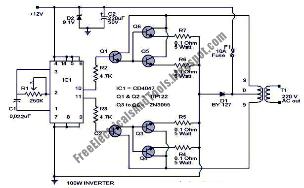
Here’s a design circuit for a 100 Watt inverter circuit using
minimum number of components. I think it is quite difficult to make a decent
one like this with further less components. Here we use CD 4047 IC from Texas
Instruments for generating the 100 Hz pulses and four 2N3055
transistors for driving the load. Here’s a design figure of the circuit
schematic;
 The IC1
Cd4047 wired as an astable multi vibrator produces two 180 degree out of phase
100 Hz pulse trains. These pulse trains are pre-amplifed by the two TIP122
transistors. The out puts of the TIP 122 transistors are amplified by four 2N
3055 transistors (two transistors for each half cycle) to drive the inverter
transformer. The 220V AC will be available at the secondary of the transformer.
Nothing complex just the elementary inverter principle and the circuit works
great for small loads like a few bulbs or fans.If you need just a low cost
inverter in the region of 100 W, then this is the best.
The IC1
Cd4047 wired as an astable multi vibrator produces two 180 degree out of phase
100 Hz pulse trains. These pulse trains are pre-amplifed by the two TIP122
transistors. The out puts of the TIP 122 transistors are amplified by four 2N
3055 transistors (two transistors for each half cycle) to drive the inverter
transformer. The 220V AC will be available at the secondary of the transformer.
Nothing complex just the elementary inverter principle and the circuit works
great for small loads like a few bulbs or fans.If you need just a low cost
inverter in the region of 100 W, then this is the best.
Subscribe to:
Posts (Atom)


