
Here’s a design circuit for a 100 Watt inverter circuit using
minimum number of components. I think it is quite difficult to make a decent
one like this with further less components. Here we use CD 4047 IC from Texas
Instruments for generating the 100 Hz pulses and four 2N3055
transistors for driving the load. Here’s a design figure of the circuit
schematic;
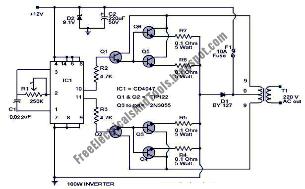 The IC1
Cd4047 wired as an astable multi vibrator produces two 180 degree out of phase
100 Hz pulse trains. These pulse trains are pre-amplifed by the two TIP122
transistors. The out puts of the TIP 122 transistors are amplified by four 2N
3055 transistors (two transistors for each half cycle) to drive the inverter
transformer. The 220V AC will be available at the secondary of the transformer.
Nothing complex just the elementary inverter principle and the circuit works
great for small loads like a few bulbs or fans.If you need just a low cost
inverter in the region of 100 W, then this is the best.
The IC1
Cd4047 wired as an astable multi vibrator produces two 180 degree out of phase
100 Hz pulse trains. These pulse trains are pre-amplifed by the two TIP122
transistors. The out puts of the TIP 122 transistors are amplified by four 2N
3055 transistors (two transistors for each half cycle) to drive the inverter
transformer. The 220V AC will be available at the secondary of the transformer.
Nothing complex just the elementary inverter principle and the circuit works
great for small loads like a few bulbs or fans.If you need just a low cost
inverter in the region of 100 W, then this is the best.


